What is the use of transistor in electronics?
What is the use of transistor in electronics?
Transistors: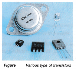
- A transistor is an electronic device which has three terminals labelled as base, collector and emitter.
- It is a solid state electronic device that has many functions such as being a switch, amplifier, voltage stabiliser and signal modulator.
- Transistors are made by joining the n-type semiconductors and p-type semiconductors together.
Transistor Types and Symbols
- There are two types of transistors, the npn transistor and pnp transistor.
- An npn transistor consists of a tljin layer.of p-type semiconductor sandwiched by two layers of n-type semiconductors. In an npn transistor, both the collector and emitter are n-type semiconductors while the base is a p-type semiconductor.
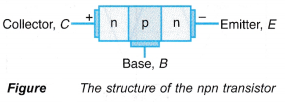
- A pnp transistor consists of a thin layer of n-type semiconductor sandwiched by two layers of p-type semiconductors. In a pnp transistor, both the collector and emitter are p-type semiconductors while the base is an n-type semiconductor.

- Figure shows the symbols for the two types of transistors, the npn transistor and the pnp transistor.

- The arrow in each of the symbol represents the direction of conventional current flow. In the npn transistor, current flows from C to E, whereas in pnp transistor, current flows from E to C.
People also ask
- How can a transistor be used as a switch?
- Understanding Semiconductor Diodes
- What do you mean by rectification?
- What is a half wave rectifier?
- What is a full wave rectifier used for?
- What do you mean by logic gates?
- What is meant by combinational logic circuits?
What is the basic function of a transistor?
- A transistor cannot function if only the collector and the emitter terminals are connected to a battery. The transistor is said to be switched off. Figure shows that when the transistor is switched off, current cannot flow through it, therefore the bulb does not light up.

- If a small battery is connected to the base as shown in Figure, to forward bias the base-emitter junction, a small current can flow through the base. This switches on the transistor. The transistor conducts and allows a larger collector current to flow through it from the collector to the emitter. Hence, the bulb lights up.

- The behaviour of the transistor shown in above Figure can be summarised as follows:
(a) If there is a small current in the base-emitter circuit, the transistor is switched on and conducts electricity.
(b) A small current in the base-emitter circuit allows a larger current to flow in the collector-emitter circuit. - These two characteristics show that a transistor can be used as a current amplifier and a control switch.
How does a transistor works as an amplifier?
Transistor as a Current Amplifier:
- The electronic equipment shown in Figure consists of amplifier circuits that are made up of transistors. The function of an amplifier circuit is to amplify a small direct current or a.c. voltage (signal).

- A transistor functions as a current amplifier by allowing a small current to control a larger current. The size of the collector current, IC, is primarily determined by the base current, IB.
- Figure shows a simple amplifier circuit used to show current amplification by measuring IB and IC.
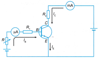
- A variable resistor R is used to control the base emitter current, IB. The output collector current, IC is observed using a milliammeter.
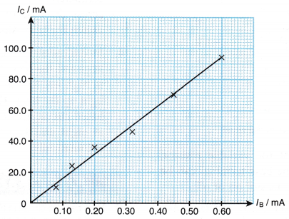
- A typical graph of IC versus IB as shown in Figure can be used to derive the current gain for the transistor used in the circuit. Note that a small change in the base current will result in a big change in the collector current.
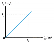
- The current amplification or the current gain can be calculated from the graph as:

Transistor Works as an Amplifier Experiment
Aim: To show a transistor acting as a current amplifier.
Materials: Transistor, resistors of 2.2 kΩ, 3.9 kΩ, 4.7 kΩ, 6.8 kΩ, 8.2 kΩ and 10.0 kΩ, connecting wires, dry cells
Apparatus: Milliammeters with range 0 – 1 mA and 0 – 100 mA
Caution: Make sure the terminals of the transistor are connected correctly to avoid damaging the transistor.
Method:
- The electrical circuit is set up as shown in Figure.
- Switch S1, is closed. The readings of the base current, Ib on the milliammeter A1 and the collector current, Ic on the milliammeter A2 are recorded.
- Step 2 is repeated with switch S1 opened and switch S2 closed. The readings of the ammeters are recorded.
- Both switches S1 and S2 are closed. The readings of the ammeters are recorded.
- Step 4 is repeated by replacing the 10.0 kΩ resistor in the base circuit with resistors of 8.2 kΩ, 6.8 kΩ, 4.7 kΩ, 3.9 kΩ and 2.2 kΩ. All the readings are recorded.
- A graph of Ic against Ib is plotted.
Results:
- S1 closed, S2 open:
Ib = 0.08 mA, Ic = 0 mA - S1 open, S2 closed:
Ib = 0 mA, Ic = 0 mA - Both S1 and S2 are closed:

- Figure shows the graph of Ic against Ib.
Discussion:
- When switch S1 is closed, milliammeter A1, gives a non-zero reading for Ib. Meanwhile milliammeter A2, gives the reading for Ic which is equal to zero. So, it can be inferred that the current flows in the base circuit only.
- When switch S1 is open and switch S2 is closed, both milliammeters A1 and A2 give a zero reading. So, it can be inferred that there is no current flow in both the base and collector circuits.
- When the base current, Ib increases, the collector current, Ic increases.
- The gradient of the graph represents the current amplification.

- A transistor amplifies current by increasing the collector current if the base current is increased. A small increase in the base current, Ib results in a big increase in the collector current, Ic.
Potential Divider
- As mentioned before, if there is a small current in the base-emitter circuit, the transistor is switched on and conducts electricity.
- Therefore, a transistor can be switched on or off by varying the voltage applied to the base terminal.
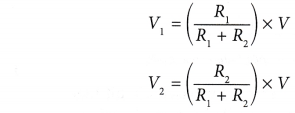
- This can be done by connecting two resistors in series across the main battery. This is called a potential divider.
- A potential divider in a transistor circuit is as shown in Figure.

- The voltages can be calculated as:
Transistor Numerical Problems and Solutions
- Figure shows the graph of Ic against Ib.
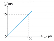
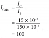
Calculate the current gain.
Solution:
- Figure shows a transistor circuit.
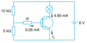
(a) What is the function of the two resistors?
(b) Find the voltage across the base of the transistor.
(c) Find the current gain.
Solution:

The post What is the use of transistor in electronics? appeared first on A Plus Topper.
from A Plus Topper
via Learning Made Simple 360
*Note that these contents are Autoblogged from A Plus Topper and cannot be edited.
Join the conversation